Nissan Juke Service and Repair Manual : B210E starter relay
DTC Logic
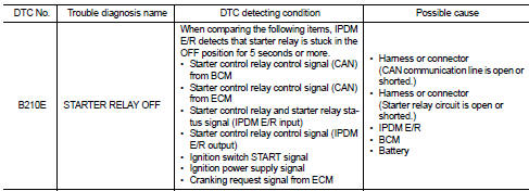
DTC DETECTION LOGIC
NOTE
:
• If DTC B210E is displayed with DTC U1000, first perform the trouble diagnosis
for DTC U1000. Refer to
PCS-59, "DTC Logic".
• If DTC B210E is displayed with DTC B209F, first perform the trouble diagnosis for DTC B209F. Refer to SEC-209, "DTC Logic".
• If DTC B210E is displayed with DTC B20A0, first perform the trouble diagnosis for DTC B20A0. Refer to SEC-211, "DTC Logic".
• When IPDM E/R power supply voltage is low (Approx. 7 - 8 V for about 1 second), the DTC B210E may be detected.
DTC CONFIRMATION PROCEDURE
1.PERFORM DTC CONFIRMATION PROCEDURE
1. Press push-button ignition switch under the following conditions to start engine, and wait 5 seconds or more.
- Selector lever: In the P position - Brake pedal: Depressed 2. Check DTC in “Self Diagnostic Result” mode of “IPDM E/R” using CONSULT-III.
Is DTC detected? YES >> Go to SEC-220, "Diagnosis Procedure".
NO >> GO TO 2.
2.PERFORM DTC CONFIRMATION PROCEDURE 2
1. Stop engine.
2. Perform DTC CONFIRMATION PROCEDURE for DTC P1650. Refer to EC-366, "DTC Logic" (MR16DDT) or EC-725, "DTC Logic" (HR16DE).
3. Turn ignition switch ON.
4. Check DTC in “Self Diagnostic Result” mode of “IPDM E/R” using CONSULT-III.
Is DTC detected? YES >> Refer to SEC-220, "Diagnosis Procedure".
NO >> INSPECTION END
Diagnosis Procedure
1.CHECK STARTER RELAY CONTROL SIGNAL
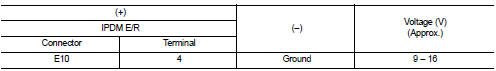
1. Turn ignition switch ON.
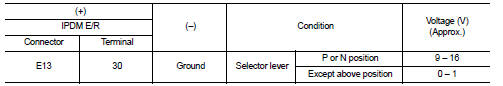
2. Check voltage between IPDM E/R harness connector and ground.
Is the inspection result normal? YES >> GO TO 4.
NO >> GO TO 2.
2.CHECK CRANKING REQUEST SIGNAL CIRCUIT
1. Turn ignition switch OFF.
2. Disconnect IPDM E/R connector.
3. Disconnect ECM connector.
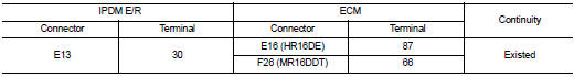
4. Check continuity between IPDM E/R harness connector and ECM harness connector.
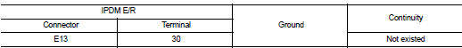
5. Check continuity between BCM harness connector and ground.
Is the inspection result normal? YES >> GO TO 3.
NO >> Repair or replace harness.
3.REPLACE ECM
Replace ECM.
Refer to EC-447, "Removal and Installation" (MR16DDT) or EC-805, "Removal and Installation" (HR16DE).
>> INSPECTION END
4.CHECK STARTER RELAY POWER SUPPLY
1. Turn ignition switch OFF.
2. Check voltage between IPDM E/R harness connector and ground.
Is the inspection result normal? YES >> GO TO 5.
NO >> Repair or replace harness. Refer to STR-12, "CVT : Wiring Diagram".
5.PERFORM DTC CONFIRMATION PROCEDURE AGAIN
1. Turn ignition switch ON.
2. Select “Self Diagnostic Result” mode of “IPDM E/R” using CONSULT-III.
3. Touch “ERASE”.
4. Perform DTC CONFIRMATION PROCEDURE for DTC B210D. Refer to SEC-218, "DTC Logic".
Is DTC detected?
YES >> Replace IPDM E/R. Refer to PCS-34, "Removal and Installation".
NO >> INSPECTION END
 B210D starter relay
DTC Logic
DTC DETECTION LOGIC
NOTE:
• If DTC B210D is displayed with DTC U1000, first perform the trouble diagnosis
for DTC U1000. Refer to
PCS-59, "DTC Logic".
• If DTC B210D is disp ...
 Hood switch
Component Function Check
1.CHECK FUNCTION
1. Select “HOOD SW” in “Data Monitor” mode of “IPDM E/R” using CONSULT-III.
2. Check “HOOD SW” indication under the following condition.
Is the indicati ...
Other materials:
Wiring diagram
IPDM E/R
Wiring Diagram
For connector terminal arrangements, harness layouts, and alphabets in a
(option abbreviation; if not
described in wiring diagram), refer to GI-12, "Connector Information/Explanation
of Option Abbreviation".
...
ANTI-HIJACK function does not operate
Diagnosis Procedure
1.CHECK “DOOR LOCK–UNLOCK SET” SETTING IN “WORK SUPPORT”
1. Select “DOOR LOCK” of “BCM” using CONSULT-III.
2. Select “DOOR LOCK-UNLOCK SET” in “WORK SUPPORT” mode.
3. Check “DOOR LOCK-UNLOCK SET” in “WORK SUPPORT”
Refer to DLK-371, "DOOR LOCK : CONSULT-III Function (BCM ...
B2267 engine speed
Description
The engine speed signal is transmitted from ECM to the combination meter via
CAN communication.
DTC Logic
DTC DETECTION LOGIC
Diagnosis Procedure
1.PERFORM SELF-DIAGNOSIS OF ECM
Perform “Self Diagnostic Result” of “ENGINE”, and repair or replace
malfunctioning parts.
>& ...
