Nissan Juke Service and Repair Manual : B210E starter relay
DTC Logic
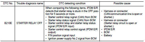
DTC DETECTION LOGIC
NOTE
:
• If DTC B210E is displayed with DTC U1000, first perform the trouble diagnosis
for DTC U1000. Refer to
PCS-30, "DTC Logic".
• If DTC B210E is displayed with DTC B2605, first perform the trouble diagnosis for DTC B2605. Refer to SEC-90, "DTC Logic".
• When IPDM E/R power supply voltage is low (Approx. 7 - 8 V for about 1 second), the DTC B210E may be detected.
DTC CONFIRMATION PROCEDURE
1.PERFORM DTC CONFIRMATION PROCEDURE
1. Press push-button ignition switch under the following conditions to start engine, and wait 5 seconds or more.
- Selector lever: In the P position - Brake pedal: Depressed 2. Check DTC in “Self Diagnostic Result” mode of “IPDM E/R” using CONSULT-III.
Is DTC detected? YES >> Go to SEC-148, "Diagnosis Procedure".
NO >> GO TO 2.
2.PERFORM DTC CONFIRMATION PROCEDURE 2
1. Stop engine.
2. Perform DTC CONFIRMATION PROCEDURE for DTC P1650. Refer to EC-366, "DTC Logic" (MR16DDT) or EC-725, "DTC Logic" (HR16DE).
3. Turn ignition switch ON.
4. Check DTC in “Self Diagnostic Result” mode of “IPDM E/R” using CONSULT-III.
Is DTC detected? YES >> Refer to SEC-146, "Diagnosis Procedure".
NO >> INSPECTION END
Diagnosis Procedure
1.INSPECTION START
Perform inspection in accordance with procedure that confirms DTC.
Which procedure confirms DTC? DTC confirmation procedure 1>>GO TO 2.
DTC confirmation procedure 2>>GO TO 5.
2.CHECK STARTER RELAY OUTPUT SIGNAL
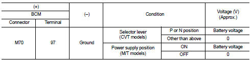
1. Check voltage between BCM harness connector and ground.
Is the inspection result normal? YES >> GO TO 4.
NO >> GO TO 3.
3.CHECK STARTER RELAY OUTPUT SIGNAL CIRCUIT
1. Turn ignition switch OFF.
2. Disconnect BCM connector.
3. Disconnect IPDM E/R connector.
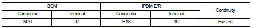
4. Check continuity between BCM harness connector and IPDM E/R harness connector.
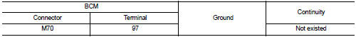
5. Check continuity between BCM harness connector and ground.
Is the inspection result normal? YES >> Replace IPDM E/R. Refer to PCS-34, "Removal and Installation".
NO >> Repair or replace harness.
4.CHECK STARTER RELAY CIRCUIT
1. Turn ignition switch OFF.
2. Disconnect IPDM E/R connector.
3. Check voltage between IPDM E/R harness connector and ground.
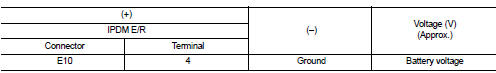
Is the inspection result normal? YES >> GO TO 7.
NO >> Check harness for open or short between IPDM E/R and battery. Refer to PCS-27, "Wiring Diagram".
5.CHECK IGNITION POWER SUPLLY NO.2 SIGNAL
1. Turn ignition switch OFF.
2. Disconnect IPDM E/R connector.
3. Check voltage between IPDM E/R harness connector and ground.
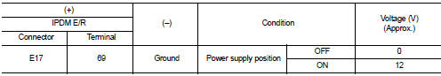
Is the inspection result normal? YES >> Replace IPDM E/R. Refer to PCS-34, "Removal and Installation".
NO >> GO TO 6.
6.CHECK BCM INPUT SIGNAL CIRCUIT
1. Disconnect BCM connector.
2. Check continuity between IPDM E/R harness connector and BCM harness connector.
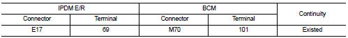
3. Check continuity between transmission range switch harness connector and ground.
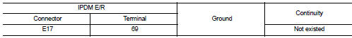
Is the inspection result normal? YES >> GO TO 7.
NO >> Repair or replace harness.
7.REPLACE BCM
1. Replace BCM. Refer to BCS-93, "Removal and Installation".
2. Perform DTC CONFIRMATION PROCEDURE for DTC B210E. Refer to SEC-148, "DTC Logic".
Is the inspection result normal? YES >> INSPECTION END
NO >> Replace IPDM E/R. Refer to PCS-34, "Removal and Installation".
 B210D starter relay
DTC Logic
DTC DETECTION LOGIC
NOTE:
If DTC B210D is displayed with DTC U1000, first perform the trouble diagnosis
for DTC U1000. Refer to PCS-
30, "DTC Logic".
DTC CONFIRMATION PROC ...
 B210F shift position/clutch interlock switch
DTC Logic
DTC DETECTION LOGIC
NOTE:
If DTC B210F is displayed with DTC U1000, first perform the trouble diagnosis
for DTC U1000. Refer to PCS-
30, "DTC Logic".
DTC CONFIRMATION PROC ...
Other materials:
Refrigerant pressure sensor
Component Function Check
1.CHECK REFRIGERANT PRESSURE SENSOR OVERALL FUNCTION
1. Start engine and warm it up to normal operating temperature.
2. Turn A/C switch and blower fan switch ON.
3. Check the voltage between ECM harness connector and ground.
Is the inspection result normal?
YES >& ...
Seat belt maintenance
• To clean the seat belt webbing, apply a mild soap solution or any solution
recommended for cleaning upholstery or carpets.
Then wipe with a cloth and allow the seat belts to dry in the shade. Do not allow
the seat belts to retract until they are completely dry.
• If dirt builds up in the sho ...
RHD
RHD : Wiring Diagram
For connector terminal arrangements, harness layouts, and alphabets in a
(option abbreviation; if not
described in wiring diagram), refer to GI-12, "Connector Information/Explanation
of Option Abbreviation".
...
