Nissan Juke Service and Repair Manual : B1183 lap Pre-tensioner LH
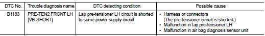
DTC Logic
DTC CONFIRMATION PROCEDURE
1.CHECK SELF-DIAGNOSTIC RESULT
 With CONSULT-III
1. Turn ignition switch ON.
2. Perform “Self Diagnostic Result” mode of “AIR BAG” using CONSULT-III.
 Without CONSULT-III
1. Turn ignition switch ON.
2. Check the air bag warning lamp status. Refer to SRC-12, "On Board Diagnosis Function".
NOTE
:
SRS does not enter diagnosis mode if no malfunction is detected in user mode.
Is malfunctioning part detected? YES >> Refer to SRC-135, "Diagnosis Procedure".
NO >> INSPECTION END
Diagnosis Procedure
WARNING:
• Before servicing, turn ignition switch OFF, disconnect battery negative
terminal and wait at least 3
minutes. (To discharge backup capacitor.)
• Never use unspecified tester or other measuring device.
1.CHECK HARNESS CONNECTOR
Check the harness connector.
Is the inspection result normal? YES >> GO TO 2.
NO >> Replace harness connector.
2.CHECK WIRING HARNESS
Check the wiring harness externals.
Is the inspection result normal? YES >> GO TO 3.
NO >> Replace wiring harness.
3.REPLACE LAP PRE-TENSIONER LH
1. Replace lap pre-tensioner LH. Refer to SR-33, "Removal and Installation".
2. Perform DTC confirmation procedure. Refer to SRC-135, "DTC Logic".
Is DTC detected? YES >> GO TO 4.
NO >> INSPECTION END
4.REPLACE AIR BAG DIAGNOSIS SENSOR UNIT
1. Replace air bag diagnosis sensor unit. Refer to SR-30, "Removal and Installation".
2. Perform DTC confirmation procedure. Refer to SRC-135, "DTC Logic".
Is DTC detected? YES >> GO TO 1.
NO >> INSPECTION END
 B1182 lap Pre-tensioner LH
DTC Logic
DTC CONFIRMATION PROCEDURE
1.CHECK SELF-DIAGNOSTIC RESULT
With CONSULT-III
1. Turn ignition switch ON.
2. Perform “Self Diagnostic Result” mode of “AIR BAG” using CONSULT-III.
With ...
 B1184 lap Pre-tensioner LH
DTC Logic
DTC CONFIRMATION PROCEDURE
1.CHECK SELF-DIAGNOSTIC RESULT
With CONSULT-III
1. Turn ignition switch ON.
2. Perform “Self Diagnostic Result” mode of “AIR BAG” using CONSULT-III.
With ...
Other materials:
P0710 transmission fluid temperature sensor A
DTC Logic
DTC DETECTION LOGIC
DTC CONFIRMATION PROCEDURE
CAUTION:
Always drive vehicle at a safe speed.
NOTE:
If “DTC CONFIRMATION PROCEDURE” has been previously performed, always turn
ignition switch
OFF and wait at least 10 seconds before performing the next test.
After the repair, p ...
Door lock status indicator
Component Function Check
1.CHECK FUNCTION
1. Select “DOOR LOCK” of “BCM” using CONSULT-III.
2. Select “DOOR LOCK IND” in “ACTIVE TEST” mode.
3. Check that the function operates normally according to the following
conditions.
Is the inspection result normal?
YES >> Door lock status in ...
P1652 starter motor system COMM
Description
ECM controls ON/OFF state of the starter relay, according to the engine and
vehicle condition. Models with no
Intelligent Key System transmit a control signal directly to IPDM E/R. On the
other hand, models with the Intelligent
Key System transmit a control signal to IPDM E/R by w ...
