Nissan Juke Service and Repair Manual : B1067, B1072 passenger air bag module
DTC Logic
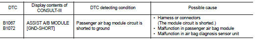
DTC DETECTION LOGIC
DTC CONFIRMATION PROCEDURE
1.CHECK SELF-DIAG RESULT
 With CONSULT-III
1. Turn ignition switch ON.
2. Perform “Self Diagnostic Result” mode of “AIR BAG” using CONSULT-III.
 Without CONSULT-III
1. Turn ignition switch ON.
2. Check the air bag warning lamp status. Refer to SRC-12, "On Board Diagnosis Function".
NOTE
:
SRS does not enter the diagnosis mode if no malfunction is detected in the user
mode.
Is malfunctioning part detected? YES >> Refer to SRC-58, "Diagnosis Procedure".
NO >> INSPECTION END
Diagnosis Procedure
WARNING:
• Before servicing, turn ignition switch OFF, disconnect battery negative
terminal, and wait at least 3
minutes or more. (To discharge backup capacitor.)
• Never use unspecified tester or other measuring device.
1.CHECK HARNESS CONNECTOR
Check the harness connector.
Is the inspection result normal? YES >> GO TO 2.
NO >> Replace harness connector.
2.CHECK WIRING HARNESS
Check the wiring harness externals.
Is the inspection result normal? YES >> GO TO 3.
NO >> Replace wiring harness.
3.REPLACE AIR BAG DIAGNOSIS SENSOR UNIT
1. Replace air bag diagnosis sensor unit. Refer to SR-30, "Removal and Installation".
2. Perform DTC confirmation procedure. Refer to SRC-58, "DTC Logic".
Is DTC detected? YES >> GO TO 4.
NO >> INSPECTION END
4.REPLACE PASSENGER AIR BAG MODULE
1. Replace passenger air bag module. Refer to SR-19, "Removal and Installation".
2. Perform DTC confirmation procedure. Refer to SRC-58, "DTC Logic".
Is DTC detected?
YES >> GO TO 1.
NO >> INSPECTION END
 B1066, B1071 passenger air bag module
DTC Logic
DTC DETECTION LOGIC
DTC CONFIRMATION PROCEDURE
1.CHECK SELF-DIAG RESULT
With CONSULT-III
1. Turn ignition switch ON.
2. Perform “Self Diagnostic Result” mode of “AIR BAG” using CONSU ...
 B1068, B1073 passenger air bag module
DTC Logic
DTC DETECTION LOGIC
DTC CONFIRMATION PROCEDURE
1.CHECK SELF-DIAG RESULT
With CONSULT-III
1. Turn ignition switch ON.
2. Perform “Self Diagnostic Result” mode of “AIR BAG” using CONSU ...
Other materials:
Squeak and rattle trouble diagnoses
Work Flow
CUSTOMER INTERVIEW
Interview the customer if possible, to determine the conditions that exist
when the noise occurs. Use the Diagnostic
Worksheet during the interview to document the facts and conditions when the
noise occurs and any of
the customer's comments; refer to DLK-139, &q ...
P1715 input speed sensor
Description
ECM receives input speed sensor signal from TCM via the CAN communication
line. ECM uses this signal for
engine control.
DTC Logic
DTC DETECTION LOGIC
NOTE:
• If DTC P1715 is displayed with DTC UXXXX, first perform the trouble diagnosis
for DTC UXXXX.
• If DTC P1715 is display ...
Precaution for Supplemental Restraint System (SRS) "AIR BAG" and "SEAT
BELT PRE-TENSIONER"
The Supplemental Restraint System such as “AIR BAG” and “SEAT BELT PRE-TENSIONER”,
used along
with a front seat belt, helps to reduce the risk or severity of injury to the
driver and front passenger for certain
types of collision. This system includes seat belt switch inputs and dual stage
f ...
