Nissan Juke Service and Repair Manual : Air cleaner and air duct
Exploded View
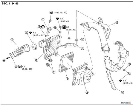
1. Mass air flow sensor
2. Gasket
3. Clamp
4. Air duct (suction side)
5. Clamp
6. Air cleaner cover assembly
7. Mounting rubber
8. Air cleaner filter
9. Air cleaner body assembly
10. Air duct with resonator
11. Grommet
12. Air duct (duct side)
13. Grommet
14. Bracket
15. Mounting rubber
A. To turbocharger
 : N·m (kg-m, in-lb)
 : Always replace after every
disassembly.
Removal and Installation
REMOVAL
NOTE:
Mass air flow sensor is removable under the car-mounted condition.
1. Remove air duct (duct side).
2. Remove engine cover. Refer to EM-25, "Exploded View".
3. Remove the air cleaner filter from the air cleaner case.
4. Disconnect mass air flow sensor harness connector, and remove harness clamp from air cleaner body.
5. Remove air cleaner body assembly.
6. Remove the air duct (between air cleaner case assembly and turbocharger air duct).
• Add matching marks if necessary for easier installation.
7. Remove air cleaner cover assembly.
8. Remove mass air flow sensor from air cleaner cover, if necessary.
CAUTION:
Handle the mass air flow sensor with following cares.
• Never shock the mass air flow sensor.
• Never disassemble the mass air flow sensor.
• Never touch the sensor of the mass air flow sensor.
9. Remove air duct with resonator with the following procedure.
a. Remove fender protector (LH). Refer to EXT-22, "Exploded View".
b. Remove air duct with resonator.
INSTALLATION
Note the following, and install in the reverse order of removal.
• Align marks. Attach each joint. Screw clamps firmly.
• Fixing clips shall be fixed after inserting air cleaner body assembly protrusion to air cleaner case botch hole.
• Make sure whether air cleaner body has been firmly installed by shaking it.
Inspection
INSPECTION AFTER REMOVAL
Inspect air duct and resonator assembly for crack or tear.
• If anything found, replace air duct and resonator assembly.
 Engine cover
Exploded View
1. Engine cover
2. Mounting rubber
Removal and Installation
REMOVAL
Remove engine cover.
CAUTION:
Never damage or scratch engine cover when installing or removing.
INSTALLA ...
 Intake manifold
Exploded View
1. Clamp
2. Water hose
3. PCV hose
4. Clamp
5. Gasket
6. Intake manifold
7. Clamp
8. Vacuum hose
9. Vacuum gallery assembly
10. Clamp
11. EVAP hose
12. EVAP servic ...
Other materials:
Power supply and ground circuit
Diagnosis Procedure
1.CHECK ABS ACTUATOR AND ELECTRIC UNIT (CONTROL UNIT) IGNITION POWER
SUPPLY
1. Turn the ignition switch OFF.
2. Disconnect ABS actuator and electric unit (control unit) harness connector.
3. Check voltage between ABS actuator and electric unit (control unit) harness
conne ...
B210E starter relay
DTC Logic
DTC DETECTION LOGIC
NOTE:
• If DTC B210E is displayed with DTC U1000, first perform the trouble diagnosis
for DTC U1000. Refer to
PCS-30, "DTC Logic".
• If DTC B210E is displayed with DTC B2605, first perform the trouble diagnosis
for DTC B2605. Refer to
SEC-90, "D ...
4WD branch line circuit
Diagnosis Procedure
1.CHECK CONNECTOR
1. Turn the ignition switch OFF.
2. Disconnect the battery cable from the negative terminal.
3. Check the following terminals and connectors for damage, bend and loose
connection (unit side and connector
side).
- 4WD control module
- Harness connecoto ...
