Nissan Juke Service and Repair Manual : ABS actuator and electric unit (control unit)
Exploded View
LHD
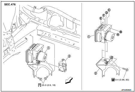
1. ABS actuator and electric unit (control
unit)
2. ABS actuator and electric unit (control
unit) harness connector
3. Bracket
A. To master cylinder secondary side
B. To master cylinder primary side
C. To front LH caliper
D. To rear RH caliper
E. To rear LH caliper
F. To front RH caliper
 : Vehicle front
 : N·m (kg-m, ft-lb)
 : N·m (kg-m, in-lb)
RHD
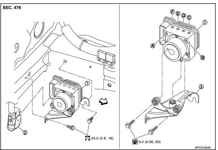
1. ABS actuator and electric unit (control
unit)
2. ABS actuator and electric unit (control
unit) harness connector
3. Bracket
A. To master cylinder secondary side
B. To master cylinder primary side
C. To front LH caliper
D. To rear RH caliper
E. To rear LH caliper
F. To front RH caliper
: Vehicle front
: N·m (kg-m, ft-lb)
: N·m (kg-m, in-lb)
Removal and Installation
REMOVAL
1. Disconnect battery cable from negative terminal.
2. Drain brake fluid.
• LHD: Refer to BR-12, "Draining".
• RHD: Refer to BR-80, "Draining".
3. Remove air cleaner case and air duct. (RHD) Refer to EM-161, "Removal and Installation".
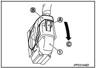
4. Disconnect ABS actuator and electric unit (control unit) harness connector (1), follow the procedure described below.
a. Push the pawl (A).
b. Move the lever (B) in the direction (C) until locked.
c. Disconnect ABS actuator and electric unit (control unit) harness connector.
5. Loosen flare nut of brake tube using a flare nut wrench, and then remove brake tube from ABS actuator and electric unit (control unit).
• LHD Refer to BR-24, "FRONT : Exploded View".
• RHD Refer to BR-91, "FRONT : Exploded View".
6. Remove ABS actuator and electric unit (control unit) and bracket.
CAUTION
:
• Never remove and never install ABS actuator and electric unit (control unit)
by holding harness
connector.
• Be careful not to drop ABS actuator and electric unit (control unit) and apply excessive impact to it.
7. Remove bracket and bushing from ABS actuator and electric unit (control unit).
INSTALLATION
Note the following, and install in the reverse order of removal.
• When replacing with a new ABS actuator and electric unit (control unit), never remove the protector of the brake tube mounting hole until right before the brake tube is installed.
• When installing brake tube, tighten to the specified torque using a flare nut torque wrench so that flare nut and brake tube are not damaged.
- LHD: Refer to BR-24, "FRONT : Exploded View".
- RHD: Refer to BR-91, "FRONT : Exploded View".
• Never remove and install ABS actuator and electric unit (control unit) by holding actuator harness.
• Bleed air from brake piping after installation.
- LHD: Refer to BR-13, "Bleeding Brake System".
- RHD: Refer to BR-81, "Bleeding Brake System".
• Never apply excessive impact to actuator, such as by dropping it.
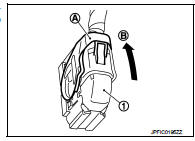
• After installing the ABS actuator and electric unit (control unit) harness connector (1), move the lever (A) in the direction (B) to secure the locking.
 Sensor rotor
Front sensor rotor : Removal and Installation
REMOVAL
Replace wheel hub as an assembly when replacing because sensor rotor cannot
be disassembled. Refer to
FAX-43, "Removal and Installation& ...

Other materials:
Additional service when removing battery negative terminal
Description
• The audio unit is equipped with the anti-theft system.
• The audio unit operates after authenticating a fixed four-digit anti-theft
code.
• After removing the battery of the audio unit, the authentication of the
anti-theft code is required.
Work Procedure
1.POWER SWITCH ON
1. ...
Back door lock
Exploded View
1. Back door lock assembly 2. TORX bolt 3. Back door striker
: Do not reuse
: N·m (kg-m, ft-lb)
: Body grease
Door lock
DOOR LOCK : Removal and Installation
REMOVAL
1. Remove the back door lower finisher. Refer to INT-35, "BACK DOOR LOWER
FINISHER : Removal and
Instal ...
Symptom diagnosis
CVT CONTROL SYSTEM
Symptom Table
The diagnosis item number indicates the order of check. Start checking in the
order from 1.
...
